To Control the process
Introducing the NEW Electronic Controller System
for the Plasmic Transition Process Engine
Our Electronic Control System (ECS)
is the precision control that makes it all work!.
Operational Sequence
To start the Plasmic Transition Process engine:
# The key (operator engine on/off switch) is turned on, thereby energizing the Electronic Control System.
# At this time the ECS comes alive, does a systems check and readies itself for operation.
# Once the base system is set, the system will accept the signal from the key being turned to the "start" position.
# It will then supply the voltage to the starter motor and starts turning the motor over. It should be noted that this could also be done from a remote or even telephonic input, say a Android pad or smart phone and even across the internet if attached
Top dead center (TDC) is the closest the piston gets to the head. As in
internal combustion motors it is the point of conversion from
fuel to power. Bottom dead center (BDC) is the farthest
point the Piston can move down the cylinder from the head.
As the piston completes its upward stroke, the piston 1 TDC
position is acquired by the micro controller from the crank
shaft mounted reluctor, or similar timing device, and the
internal position clock is synced and locked. The startup/run
RPM data is then loaded into the timing subsystem within the
controller. In the 1982 schematic this was used to reset the
multi vibrator.
The motor function is dependant on a number of design
variables, including chamber design, electro magnetic design
and the gas mixture characteristics, but as a generality, here
is how it works:
1. At about 30 degrees before TDC the cylinder containment coil(s), around the cylinder, is provided a speed related voltage to "squeeze" the gas mixture slightly. This electronically reduces the cylinder volume available. In the original electronic controller on the Papp motor, this voltage was set by the operator on a wire type rheostat. In Plasmic Transition Process's controller this voltage is set by a digitally programmable DC voltage source to follow the operator speed analog input, similar to the way of a modern accelerator.
2. At about 10 degrees before TDC the reaction voltage is applied to the reaction chamber electromagnetic coil to further initiate the ionization process of the gas mixture within the reaction chamber. In the Papp motor this is roughly equiv to Coil One. This voltage is set by a digitally controlled voltage source based on the RPM requirement in the Plasmic Transition Process controller.
3. At about 7 degrees before TDC a radio frequency, with frequency based in run speed (10 to 38 MHZ), is applied to the loop antenna within the reaction chamber ionizing the gas mixture and warming it. In the Papp motor this has to actually happen early because of the in-chamber interface. Also in the original electronic controller this was changed by the operator. In Plasmic Transition Process's controller it is adjusted by a digitally programmable RF Generator and Linear Power Amplifier as needed for the engine speed requirements.
4. At 2 degrees before TDC the HV Spark coil(s) is pulsed and this continues at 30 Hz, or as allowed by the coil, until released. In the Papp motor this had to actually happen early because of the in-chamber interface. Plasmic Transition Process redesigned the entire reaction area. Because it is still in a patent pending state, this can't be described in detail. Suffice it to say, Plasmic Transition Process, like Papp, creates an arc. But, unlike the Papp reaction system there are no radioactive components involved.
5. This continues until 12 degrees after TDC or the presence of a HV Pulse is seen by the controller from the chamber pulse sensor. This sensor also is used by the automatic refueling system and instrumental feedback to the motor status unit within the ECS. This is for efficiency as the requirement is only two atoms and the sensor makes that happen. In the Papp motor there was no control but the resistance of the system had much to do with it not going astray.
6. The resulting high voltage charge, 60 to 240 KV, is applied to the reactor electrodes causing a continuous arc across the small reactor space to ground in the Papp, and something similar in the Plasmic Transition Process motors.
7. This arc flowing through the ionized gas mixture causes the Helium in the gas mixture (or hydrogen in large volume mixtures) to join, fusing, together. Most efficiently this typically is a two atom event, as that would cause the controller, via the chamber pulse sensor, to release the trigger arc to save reactant. In the Papp this is a degree position dependent timing.
8. This event creates:
• a very high temperature, roughly 5 times the surface of the sun,
• very high power equivalent,
• and as a side effect, a white to white bluish light.
This high temperature, several times that of the sun, frees
protons and electrons, power and such. This then causes the gas
mixture to start a chaotic fission event which releases more
electrons, and transitions the gas mixture creating a plasma.
This Plasmic Transition will continue to grow as long as
ionized gas is available for conversion to a plasma, acting
similar to live steam on a piston in a steam engine. One note
about the heat . . . , the fusion event time is measured in
billionth's of a second. Typically, it is the catalyst that
starts the Plasmic Transition. Thus the heat is dispersed
between reactions and is not a cumulative factor. It is NOT
needed to maintain the process as the ionized gas will continue
as long as it is excited to do so. It is the plasma transition,
which increases the volume, as steam does, that provides the
continuing push to displace the piston toward BDC. It is this
fact that makes it possible to change speed by simply changing,
electro magnetically, the cylinder volume. The smaller the
column the quicker the fill and the sooner the piston moves
down toward BDC and removal of excitation.
9. This Plasmic Transition process multiplies the volume within the cylinder as the new plasma elements created require space. This expansion, as the gas transitions to plasma, drives the piston in a downward, linear, direction -- just as in a steam engine, which explains the torque delivery being flat across RPM.
10. This downward push is applied through the commonly understood reciprocating motor system through the connecting rod to the crankshaft turning it and passing energy across the crankshaft, storing this mechanical energy, kinetically, in the flywheel, or load, as mechanical energy via torque, measurable in foot-pounds.
11. At about 15 degrees after TDC, the RF energy excitement is released as it is no longer needed. In the Plasmic Transition Process controller this is also varied based on the motor RPM. On the Papp motor it was fixed.
12. At about 17 degrees after TDC the ionization voltage provided to the reaction chamber electromagnetic coil is reduced to the resting state voltage as it is no longer needed either. The Plasmic Transition will continue for an instant more in the Plasmic Transition Process motor. In the Papp there may not be an equivalent. The Papp chamber magnetics are very complex and difficult to simplify for explanation. In that motor several coils are switched in order to maintain a control element overall.
13. At about 155 degrees after TDC, before the piston reaches bottom dead center, the containment coil(s) voltage is reset back to the resting voltage state. This is done to release the linear pressure internally within the Cylinder and allow the plasma state, which is nearly done expanding, time to finish. The majority of the power transfer is already done.
14. After the piston reaches its maximum volume or bottom dead center (BDC) position, the gas mixture will reverse the Plasmic Transition to revert and recombine back to a steady state form -- gas -- creating a partial vacuum. Remember that the plasma is a creation from the "normal steady state" gases and sustained by the excitation of them. All reactions that create a different state will return to the best "steady" state, like ice to water. So it is with plasma returning to gas. Thus the small vacuum reduces to the one-atmosphere it was at initially.
15. The opposing cylinder will follow its sequence independent of Cylinder 1 and 180 degrees out of phase, as controlled by the electronic control system. Thus providing the equal yet opposite effect on the Crankshaft. This two stroke sequence dramatically reduces any imbalance that may result from components. With the latest Aluminum, light weight as it is over 20 Lbs lighter and the new Aluminum Rods and Plastic pistons to further reduce the reciprocating weight the new, current, engine runs like a kitten.
The same volume of gas mixture is used for reaction over and over again for an extended period of time. Loss of gas mixture is not considered because of the increased pressure during the power stroke and the vacuum during the non power stroke. So any gas leaking past the sealing rings of the pistons will be very small. The Plasmic Transition Process controller also has a refuel action to keep this from being a field problem. Plasmic Transition Process's fuel cans look like the air conditioner refueler "freon " cans used to refill a car air conditioner. They are screwed in and used as needed.
Plasmic Transition Process has defined many Gas, Noble and cross mixed, mixtures that will provide this same Plasmic Transition Process and results, but each mixture requires different control parameters or motor volumetric conditions for best performance
What About Heat Dissipation?
Plasmic Transition Process sets the maximum rotational speed of an engine at 2900 RPM. The reason for this is that every time the event occurs, there is a very large side product of heat -- four or five times the temperature of the sun -- but for only about a half billionth of a second. So that heat gets dissipated easily by the aluminum Head bulk, if it is not repeated too quickly. Plasmic Transition Process simulations show that the point where heat starts to accumulate is 3000 RPM, or 50 cycles per second. At high RPMs it would take 30 minutes to get up to 10°C over ambient. Unfortunately, the warmer the chamber the more power is required for transition. As the temperature builds up, the efficiency of the process reduces, so it would be counter productive to allow this heat build up to occur. This is why the controller has a ~2900 RPM limit.
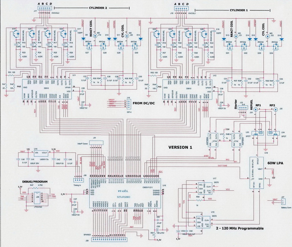
Comparing the Old and New Controllers a look at the heart of the process:
Below in Figure 2 is a advanced electronic version, using today's standards. However, this first controller was very modern for its day and was a big improvement on what Papp originally had. "No matter how you look at it, if it had it not been for this controller above this motor would have never been of interest or worked properly," says John Rohner. "This was the single most significant part of the historical running Motor. This, not some gas mixture, was why it worked. Hats off to Tom. Had it not been for him, this process would have remained a toy.".Figure 2. -- A more Modern Controller
|
|
|
Given their Electronic Control System, in Above, Plasmic Transition Process claims to have proven the motor hardware design, as well as proving that the gas mixtures can be many things.
This ECS is many times more powerful and flexible than the 1982 unit above; it provides for more flexible control of the process; and it more easily adapts to various gas mixtures, reaction chamber designs, volumes and process reactions.
Plasmic Transition Process's controllers sense the reaction and can cut the arc excitation to save fuel and extend life.
In the original electronics, a single CB RF frequency was used. In Plasmic Transition Process's controllers they tune this RF energy over a range from 10 to 38 MHz to best optimize the excitation per the motor's speed.
In the original, there had to be multiple batteries for "Run" voltages. Plasmic Transition Process solved that with a programmable DC to DC converter. So their controller runs from a single battery source creating the voltages it needs to operate.
They also sense cylinder reaction power output, so they know when to "refuel"; and they expect to be able to do this automatically on the run.
They also communicate with other ECS systems as well as the user. This is important in multiple cylinder motors to keep the cylinders in sync and balance power sharing across the complete system.
The Electronic control systems are fully programmable to take advantage of all new lessons learned as Plasmic Transition Process progresses with their objective of replacing internal combustion motors, as well as finding uses that have not yet been conceived. "Plasmic Controls, Inc.", a sister company, is the focal point for any innovative thinking along these lines.
Control Systems Consulting works with Each Engine Manufacturer's operational characteristics as well to provide the best economy and power available for that engine/Gas mix combination per specification to maintain the best overall fully integrated experience.
Figure 3 :
A modern Electronic Engine Control System BLOCK Diagram [Process Flow]from Plasmic Transition Process, by it's controller development company: Plasmic Control, Inc.
|
|
|